Semantic Message Flow Diagram
The Semantic Message Flow Diagram (message flow diagram) is a diagramming method that integrates control flow and data flow using a single flow notation. It represents both system-internal behavior and information propagation with a unified causal line, and can be used for architectural descriptions and extensions of robustness diagrams.
Semantic Message Flow Diagram
When creating model diagrams that describe system architecture, one major challenge is how to handle control flow and data flow. In flows such as data retrieval, the direction of the control-flow arrow and the data-flow arrow becomes reversed.
To address this, SimpleModeling proposes the Semantic Message Flow Diagram, a notation that allows control flow and data flow to coexist within a unified representation. Its abbreviated name is “Message Flow Diagram.”
Using this diagram, the following types of information can be expressed:
-
Direction of control and data
-
Synchronous vs. asynchronous
-
Push vs. pull
-
Differences between logical and physical flows
-
Information structures such as caching or synchronization
This diagramming method will be used throughout SimpleModeling.org in articles and model explanations where appropriate.
Syntax
In a Message Flow Diagram, nodes may be represented using any shape.
Nodes are connected using message-flow notation lines.
This section describes the syntax of flow lines used in the Message Flow Diagram.

Meaning of Lines
-
Solid line: Indicates synchronous communication. After control transfer, the sender waits for the receiver to complete its processing.
-
Dashed line: Indicates asynchronous communication.
Control Flow
-
Destination: Line arrow (→)
-
Source: No symbol
This flow represents control transfer without data transmission. Passing parameters or lightweight information is possible, but its primary meaning is the delegation of control.
A solid line indicates synchronous flow, while a dashed line indicates asynchronous flow.
Data Push
-
Destination: Black arrow (▶)
-
Source: No symbol
This flow is used when the sender actively pushes data to the receiver.
A solid line indicates synchronous flow, while a dashed line indicates asynchronous flow.
Data Pull
-
Destination: Line arrow (→)
-
Source: White arrow (▷)
The source initiates the action and pulls data from the destination. Because of this, the direction of control and data flow is reversed.
Data Push–Pull
-
Destination: Black arrow (▶)
-
Source: White arrow (▷)
Used when the source initiates both sending and receiving of data. Typical examples include exchanging a query and its corresponding result simultaneously.
Smart Push
-
Destination: No symbol
-
Source: White arrow (▷)
Logically, data flows from the source to the destination, but in actual physical cycles, the destination retrieves the data through polling. This pattern supports cache updates and asynchronous background processing.
Example Usage
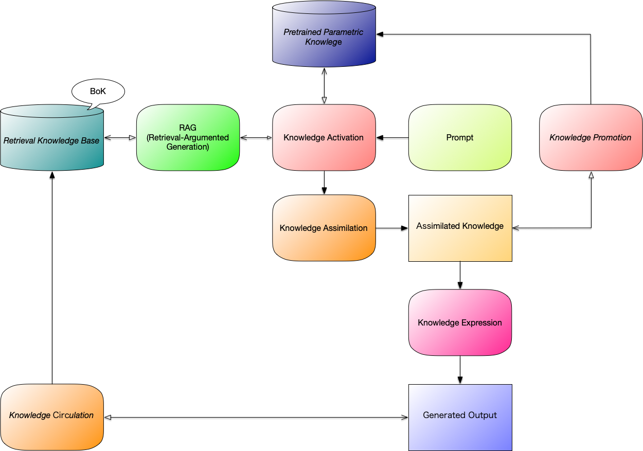
The following diagram, “Generative AI Reference Architecture,” used in 📄 AI Collaboration Architecture, employs the Semantic Message Flow Diagram.
Semantic Message Flow Notation
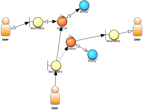
Applying the Semantic Message Flow Notation—used for connection lines in the Semantic Message Flow Diagram—to existing UML diagrams enhances their expressive power.
One strong use case is applying it to robustness diagrams. A standard robustness diagram shows only the communication paths among Actors, Boundaries, Controls, and Entities, but by using message-flow arrow symbols, both control flow and data flow become immediately visible.
References
Glossary
- Semantic Message Flow Diagram (message flow diagram)
-
A diagram that unifies the direction of control and the direction of data into a single connection line, visualizing the semantic information flow among processes, entities, and events. Each connection line (message flow) simultaneously represents the trigger for an action (control) and the transmission of information (data), expressing the semantic causal structure of actions, information, and state transitions.
- Semantic Message Flow Notation (message flow notation)
-
A connection-line notation that integrates control flow and data flow into a single representation, capturing the semantic information flow among processes, entities, and events. Each connection line simultaneously represents the trigger for an action (control) and the transmission of information (data), expressing the semantic causal structure of actions, information, and state transitions.
- Generative AI Reference Architecture
-
An architecture that organizes the internal processes executed by generative AI: knowledge activation, assimilation, expression, promotion, and circulation.
- UML (Unified Modeling Language)
-
A standardized modeling language for object-oriented analysis and design. It represents system structures and behaviors through diagrams such as class, sequence, and use case diagrams. Serves as the foundational language for UP and CBD.